
Get Free Quote
Contact us for personalized pricing
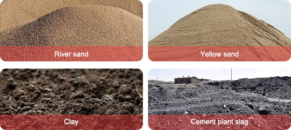
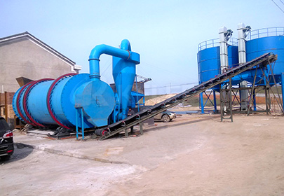
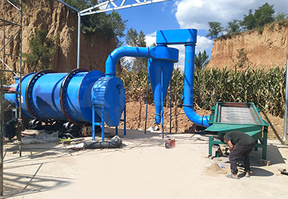
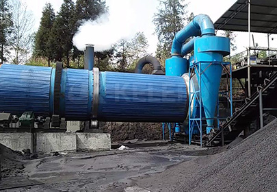
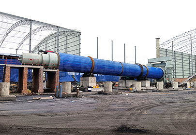
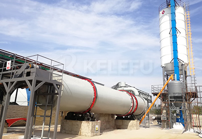
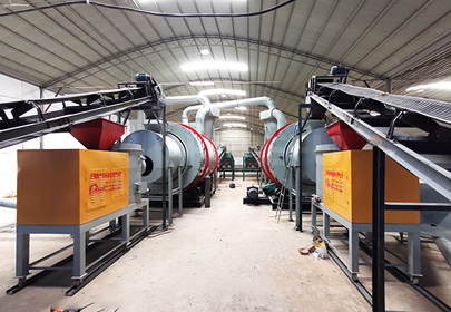
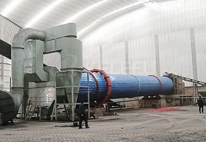
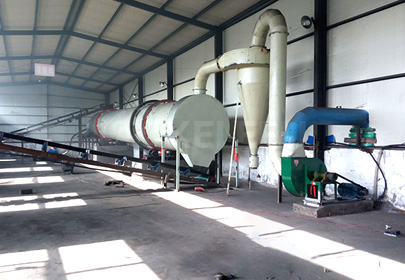
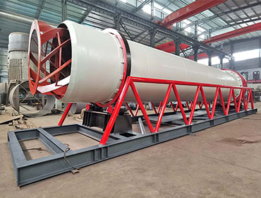
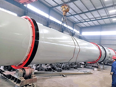
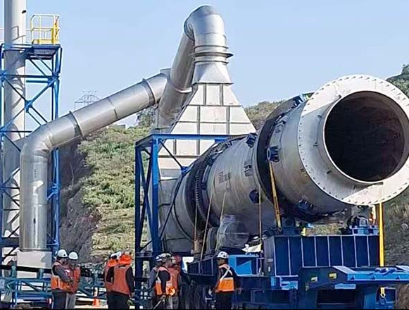
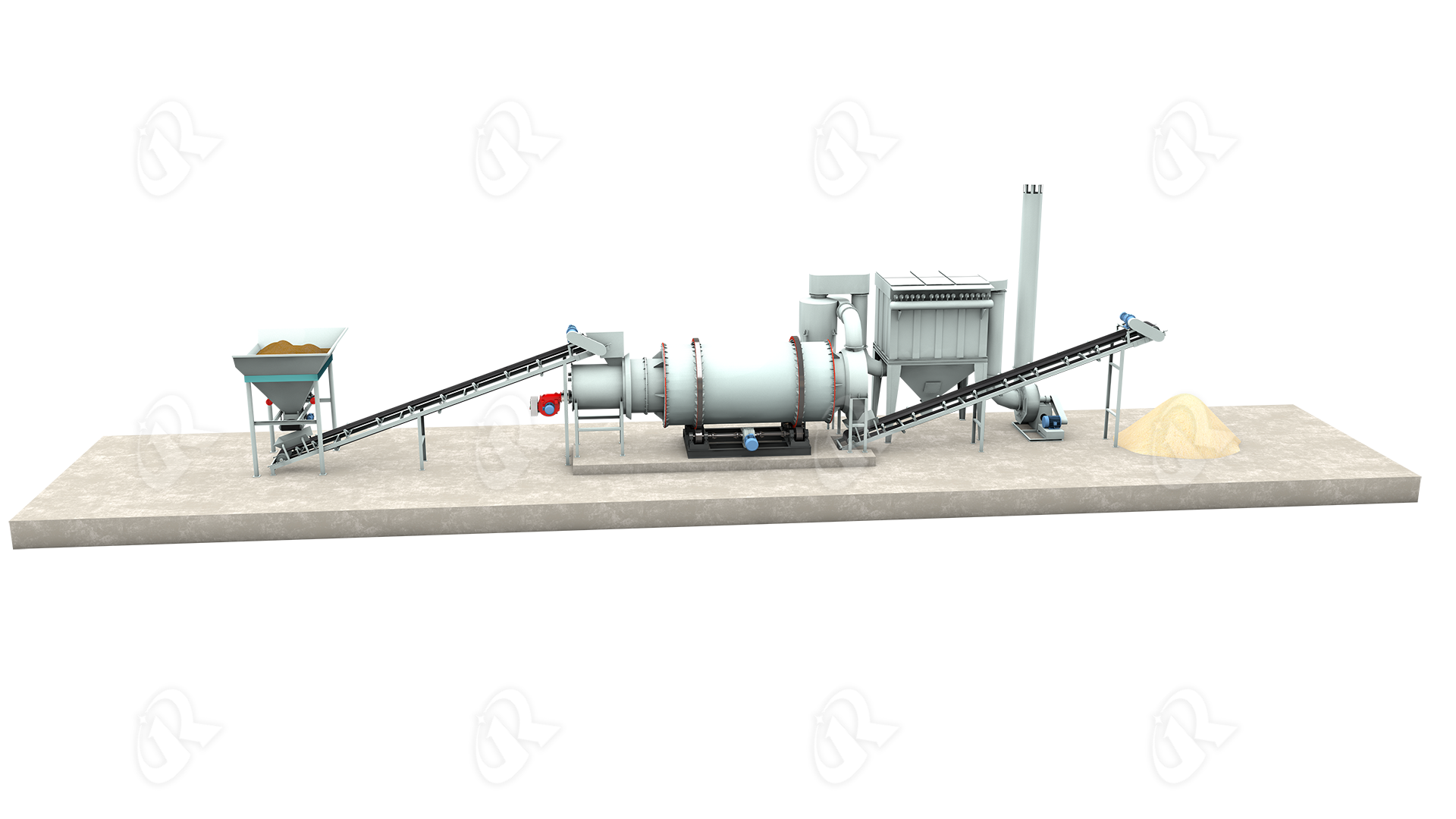
Our Sand Triple-Pass Rotary Dryer is specifically designed for various sand materials. Utilizing three concentric cylinders nested inside each other, combined with wear-resistant lifting plate systems, low-temperature high-air-volume process, and high-efficiency dust collection system, it rapidly reduces sand moisture from 5%-15% down to 0.5%-3%, while preserving grain integrity and preventing over-grinding, ensuring stable particle size distribution.
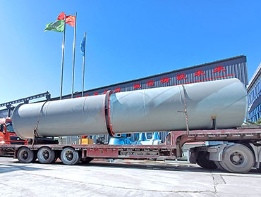
Compared with traditional single-drum dryers, the triple-pass design achieves thermal efficiency exceeding 80%, over 50% less floor space, and 40%-60% lower energy consumption. Whether for dry-mix mortar plants, silica sand processing facilities, or oilfield frac sand operations, the triple-pass sand dryer is the ideal choice.
Dried products from the Sand Dryer can be widely used in the following industries:
| Application | Typical Materials | Post-Drying Use | Value Proposition |
|---|---|---|---|
| Dry-Mix Mortar | Dried sand | Masonry mortar, plastering mortar, flooring mortar | Moisture <0.5%, ensures mortar quality, prevents caking |
| Concrete Batching Plants | River sand, manufactured sand | Ready-mix concrete, precast components | Controls moisture content, ensures mix proportion accuracy, improves strength |
| Asphalt Mixing Plants | Sand, fine aggregate | Asphalt mixture | Ultra-low moisture prevents asphalt foaming, improves pavement quality |
| Glass Manufacturing | Silica sand | Glass raw material | Removes moisture, improves melting efficiency, reduces energy consumption |
| Foundry Industry | Silica sand, resin sand | Foundry molding sand | Uniform drying ensures mold strength and casting surface quality |
| Oilfield Fracking | Frac sand (silica sand) | Hydraulic fracturing proppant | Moisture <0.5%, ensures flowability, prevents clumping and blockage |
| Building Materials / Chemicals | Various industrial sands | Fillers, filter materials | Dewatering facilitates storage and transport |
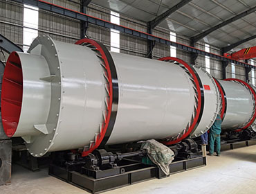
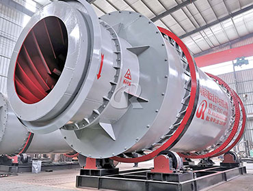
This Sand Triple-Pass Rotary Dryer utilizes three concentric cylinders nested inside each other, dividing the drying process into three stages, with special reinforcement for the highly abrasive and dust-prone characteristics of sand:
Stage One: Outer Cylinder (Co-current Drying)
Wet sand (5%-15% moisture) is fed into the outer cylinder via a belt conveyor or bucket elevator. A wear-resistant chute at the feed end ensures uniform entry. A hot air furnace generates 200°C-400°C hot air, which flows co-currently with the material, rapidly evaporating surface moisture. Large-lift-angle combined lifting plates on the inner wall continuously lift and drop the sand, forming a uniform "material curtain" that maximizes heat exchange area.
Stage Two: Middle Cylinder (Counter-current Deep Drying)
Material enters the middle cylinder where hot air flows in the opposite direction. The middle cylinder is surrounded by the outer and inner cylinders, creating a self-insulating system—heat dissipated from the inner and outer cylinders is absorbed by the material in the middle, achieving full thermal utilization and significantly improving thermal efficiency. This stage provides deep dewatering, removing fissure water from within the sand particles.
Stage Three: Inner Cylinder (Reciprocating Uniform Drying)
Material enters the inner cylinder where moisture has been significantly reduced. Under the action of specially designed rectangular multi-loop lifting plates, the material moves in a "two steps forward, one step back" pattern, extending residence time and ensuring uniform drying. Final moisture is stably controlled at 0.5%-3%.
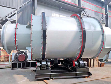
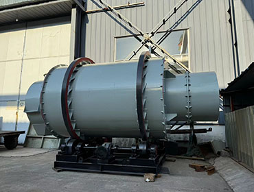
Wear-Resistant Design: Sand has high hardness (Mohs hardness 7) and is extremely abrasive. The cylinder is made of wear-resistant steel or lined with high-manganese steel liners, and lifting plates undergo hardfacing welding treatment, extending service life by 2-3 times.
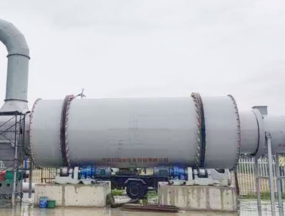
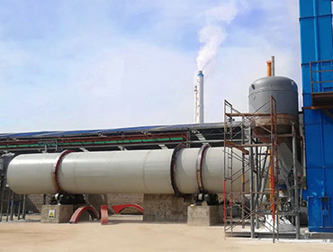
Dust Control Design: Fully sealed negative pressure operation with high-efficiency pulse baghouse filter achieves dust emissions below 20mg/Nm³.
Gas-Solid Separation: Dried sand is discharged via a discharger, while dust-laden exhaust gas enters the dust collector for purification before emission.
| Specifications and Models | Handling capacity drying sand(t/h) | finished product Moisture(%) | Power(KW) |
| KLF-TH1630 | 3-5 | <2±1 | 4 |
| KLF-TH2240 | 6-8 | <2±1 | 4 |
| KLF-TH2460 | 10-15 | <2±1 | 7.5 |
| KLF-TH2660 | 15-20 | <2±1 | 15 |
| KLF-TH2870 | 25-30 | <2±1 | 18.5 |
| KLF-TH3080 | 30-40 | <2±1 | 22 |
| KLF-TH3290 | 40-50 | <2±1 | 45 |
| KLF-TH3390 | 50-60 | <2±1 | 55 |
| KLF-TH3610 | 70-80 | <2±1 | 75 |
| The above parameters are for reference only. For more details, please contact customer service | |||
We're here to help with all your inquiries. Send us a message and we'll get back to you promptly.
Fill out the form below and we'll contact you soon